


All Products
-
 Bruno NascimentoThank you for your continued help and support in providing us with high-quality and affordable products.
 -
 Ehsan SalmariPrompt reply and professional attitude make our cooperation smoother!
GE DS200SDCCG4AEC Drive Control Card 330mm x 200mm x 100mm


| Place of Origin | USA |
|---|---|
| Brand Name | GE |
| Certification | COO |
| Model Number | DS200SDCCG4AEC |
| Minimum Order Quantity | 1 |
| Price | $1500 |
| Delivery Time | 5-7days |
| Payment Terms | T/T |
| Supply Ability | 999 |
Product Details
| Name | GE DS200SDCCG4AEC Drive Control Card | Product ID | DS200SDCCG4AEC |
|---|---|---|---|
| Series | Mark V | Product Net Weight | 2kg |
| Product Net Depth/Length | 330mm | Product Net Height | 200mm |
| Product Net Width | 100mm | Warranty | 1 Year |
| Highlight | GE DS200SDCCG4AEC drive control card,GE turbine control card with warranty,drive control card 330mm x 200mm |
||
Product Description
GE DS200SDCCG4AEC Drive Control Card
Product Description:
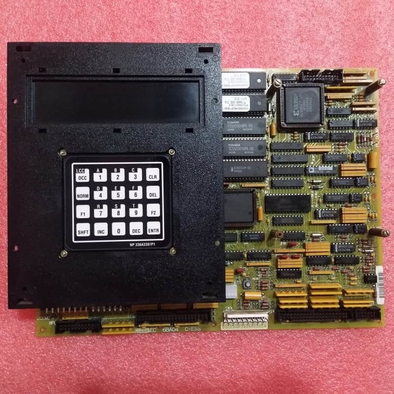
The GE DS200SDCCG4AEC is a core Drive Control Board for industrial drive systems (likely integrated with GE’s Mark V Turbine Control System), equipped with three specialized microprocessors—Drive Control Processor (DCP), Motor Control Processor (MCP), and Co-Motor Processor (CMP)—plus shared RAM for simultaneous multi-processor access. The DCP manages system-level tasks like chip select decoding, direct memory access (DMA), and interrupt control; the MCP handles motor-specific functions; and the CMP processes math-intensive tasks beyond the MCP’s capability.
It contains full drive control processing functionality, enabling signal transmission/reception with other boards, while supporting optional auxiliary cards to add LAN communication or enhanced signal processing. A front-panel array of 10 LEDs facilitates real-time function monitoring and fault detection, displaying codes in binary coded decimal (BCD) or binary based on fault severity. Configurable hardware—Berg-type JP jumpers and WJ wire jumpers—ensures alignment with system requirements.
For installation/replacement: Standoffs on the board secure optional cards; all power must be disconnected first to avoid electrocution. Cables from auxiliary cards must be disconnected, and securing screws removed before removal. Replacement requires reattaching cards/cables, using factory nylon washers to prevent screw damage, and ensuring plastic holders are tightened. EPROM modules from the defective board must also be transferred to the replacement unit, inserted gently into connectors.
Key Features:
Expandable Functionality: Supports optional LAN and signal processor cards, adapting to diverse communication or signal processing needs.
Intuitive Diagnostics: 10 LEDs with BCD/binary fault coding enable quick issue identification, reducing troubleshooting time.
Configurable Hardware: Factory-set JP/WJ jumpers ensure out-of-the-box compatibility, with flexibility for user adjustments.
Safe & Secure Installation: Requires power disconnection; includes standoffs, nylon washer compatibility, and EPROM transfer guidelines to ensure reliable, damage-free assembly.
![]()
![]()
Recommended Products